Application
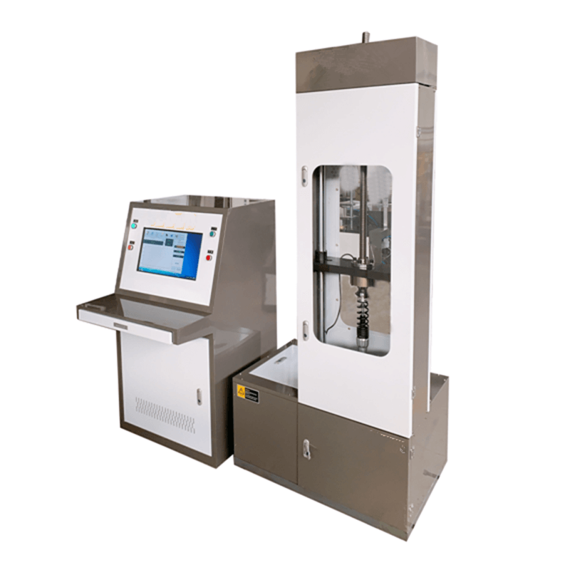
CY-JP20KN microcomputer-controlled absorber spring fatigue testing machine is mainly used for fatigue life test of various shock absorbers and barrel shock absorbers used in various tricycles, two-wheeled vehicles, automobiles, motorcycles, and other motor vehicles. Special fixtures can also be made to suit the fatigue test of special specimens.
The microcomputer-controlled absorber Spring fatigue testing machine is a high-precision, high-program-controlled high-end shock absorber fatigue testing machine based on the mature ordinary fatigue testing machine, combined with modern electronic induction, measurement and control and other high-tech methods.
Specifications
|
Name |
specification |
||
|
1 |
Maximum test force |
20KN |
|
|
2 |
Number of test stations |
1 |
|
|
3 |
Test frequency |
0.5~5Hz |
|
|
4 |
Frequency display accuracy |
0.1 Hz |
|
|
5 |
Test amplitude |
±50mm |
|
|
7 |
Maximum capacity of counter |
1 billion times |
|
|
8 |
Counting stop accuracy |
±1 |
|
|
9 |
Maximum outer diameter of test piece |
Φ90mm |
|
|
12 |
Power supply voltage (three-wire four-phase system) |
380VAC 50Hz |
|
|
13 |
main motor power |
7.5kW |
|
|
14 |
Size |
Host |
1200*800*2100(H) |
|
Control Box |
700*650*1450 |
||
|
15 |
Weight |
450kg |
|
Key Features
1.1 Host: The host is mainly composed of a frame, a mechanical loading mechanism, a transmission mechanism, and a fixture. The frame is composed of a column, a workbench, an excitation platform, an upper beam, a screw lifting mechanism, a base and other parts. The column, workbench, an excitation platform, an upper beam, and a screw lifting mechanism are installed together and stably installed on the On the base; the tested shock absorber is installed between the excitation table and the lead screw through a fixture, and the test piece of different sizes can be met by adjusting the lifting of the lead screw, and the test piece of different installation methods can be met by changing the fixture. Requirements.
1.2 Loading mechanism: It is a mechanical structure, mainly composed of a crank connecting rod mechanism, which converts the motor's rotary motion into a vertical linear reciprocating motion; by adjusting the eccentricity of the slider, the linear reciprocating motion distance can be adjusted to The test stroke required by the test piece.
1.3 Transmission system: The transmission mechanism is composed of a three-phase asynchronous motor and a flywheel. The speed of the motor can be adjusted by the frequency converter, so that the test frequency can be arbitrarily adjusted within the range of 0.5 to 5 Hz.
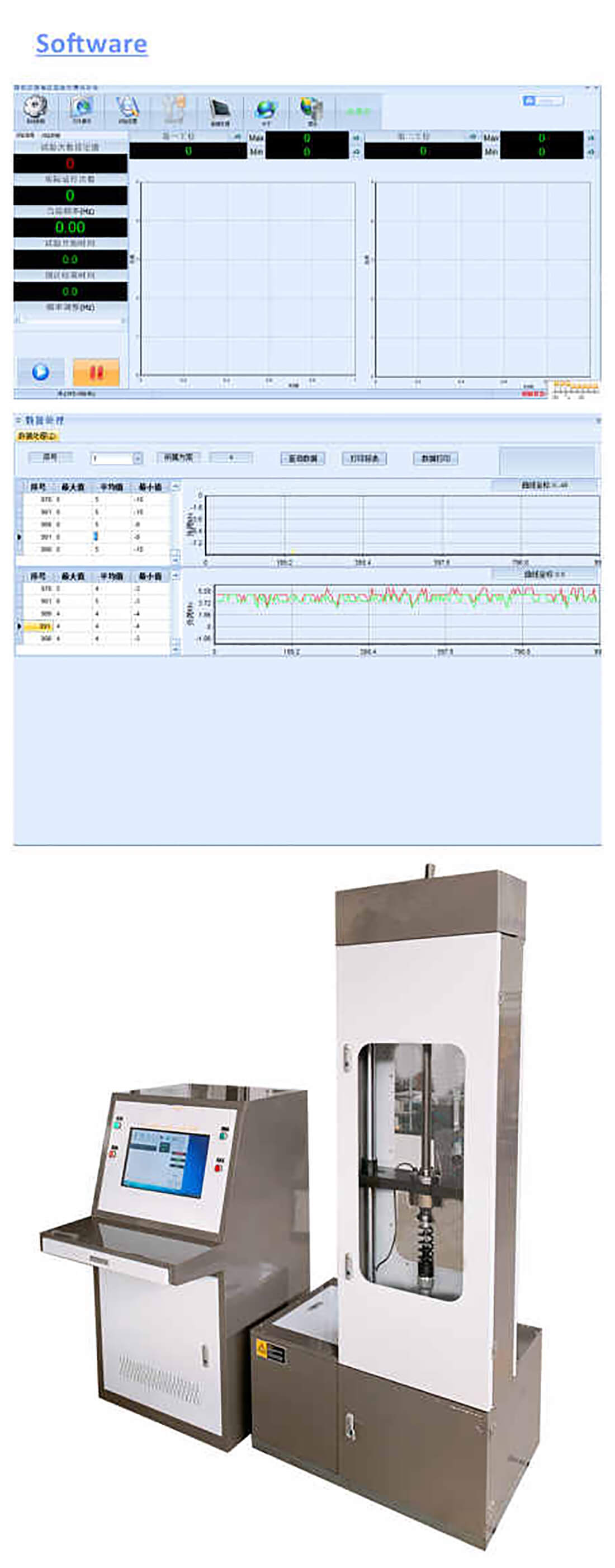
1.4 Control system: The computer measurement and control system is independently developed and produced by our company. It has a memory function, that is, historical test data can be accessed at any time. The measurement and control system is the center of the test device. On the one hand, the computer collects the test force signal of each shock absorber during the test, and displays the test force in real time, and displays various status parameters such as: test frequency, current test times, each work Load and time curve, test force attenuation, etc. On the other hand, control parameters must be set according to control requirements, such as: automatic shutdown test number setting, automatic shutdown test force setting according to stress drop, etc., for strong current control The box sends out a control signal, and the strong current controller controls the main motor, controls the adjustment mechanism of the upper and lower test spaces, protects the space adjustment function during the test, prevents wrong actions during the test, and protects the operator and equipment The security, as shown in the figure:
1.5 Software function introduction
1.5.1 The number of tests can be set. The maximum number of times capacity is 1 billion times.
1.5.2 The number of tests reaches the set number, and the test machine is controlled to stop the test.
1.5.3 The test software system displays the test frequency and the number of tests through the computer and judges the break and shutdown.
1.5.4 It has the function of automatic shutdown when the shock absorber is damaged at any station and the function of stopping when the maximum test force of the shock absorber is attenuated to the specified load.
1.5.5 It has a real-time display function of the test force-time curve of a single shock absorber, and records the load attenuation data of the shock absorber according to the sampling period set by the test plan.
1.6 The main features are as follows:
1.6.1 The amplitude and frequency can be adjusted freely.
1.6.2 Digital display of vibration times and frequency.
1.6.3 Automatic shutdown of preset test times, higher efficiency.
1.6.4 The test of a single pair of shock absorbers can be done, or the test of multiple pairs of shock absorbers can be carried out.
1.6.6 The preset number of shutdowns can be used for unattended tests;
1.6.7 There are test fixture installation screw holes;
1.6.8 Equipped with amplitude adjustment tooling, which is convenient for amplitude adjustment;


